yash

Wednesday, December 22, 2010

SIMPLE DIGITAL SECURITY SYSTEM


You can use this simple and reliable security system as a watchdog by installing the sensing loops around your building. You have to stretch the loop wires two feet above the ground to sense the unauthorised entry into your premises. Wire loops 1, 2 and 4 are connected to the A, B and C inputs of 7-segment decoder 4511 (IC1), respectively, while the D input of IC1 is grounded permanently.
The loops are also connected to a dual 3-input NOR gate and inverter CD4000 (IC2) to activate the alarm. Fig. 1 shows the circuit of the digital security system, while Fig. 2 shows the proposed wiring diagram for the loops around the premises. Before using this security system, make sure that loops shown in Fig. 2 are connected as shown in Fig. 1. If you don’t want to use a buzzer, switch it off by opening switch S2. The circuit works off a 9V regulated power supply.

 However, battery back-up is recommended. A commoncathode, 7-segment display (LTS543) is used for displaying whether the loops are intact or not. If loop 1 is broken, the display will show ‘1’. If two or all the three loops are broken, the display will show the sum of the respective broken loop numbers. For example, if loops 1 and 4 are broken, the display will show 5(1+4).


When all the three loops are intact, the display will show ‘0.’ All the three inputs of gate N1 remain low to give a high output. This high output is further given to gate N2 and, as a result, its output remains low. This keeps transistor T1 in cut-off position and the piezobuzzer does not sound. When any loop is broken, the output of NOR gate N1 goes low, while the output of gate N2 goes high. Transistor T1 conducts and the buzzer sounds to alert you. You can mute the buzzer by switching off power to the circuit through switch S1.

Motion Sensor for security Light


Here is a system based on PIR motion detector module BS1600 (or BS1700) that can be used for security or corridor lighting in power saving mode.
The 12V DC power supply required for the motion detector and the relay driver is derived from 230V, 50Hz mains using a transformerless circuit as shown in Fig. 1. The working of the circuit is simple. When you power-on the circuit after assembling all the components including the CFL, the CFL will glow for 10 seconds, turn off for 30 seconds, glow for 10 seconds and then turn off.
Now the circuit is ready to work.
When any movement is detected, around 3.3V appears on the base of relay-driver transistor T1 and it conducts to energise relay RL1. As a result, Triac1 (BT136) fires to provide full 230V and light up the CFL. Another normally-opened contact of the relay (N/O2) is used here to hold the output until reset. If the switch is not in ‘hold’ position, the light will remain ‘on’ for about ten seconds (as programmed in the motion sensor). In short, when there is a movement near the sensor, the CFL glows for about ten seconds. It will remain ‘on’ if switch S1 is in ‘hold’ position. Assemble the circuit on a general-purpose PCB and enclose in a suitable cabinet. Use a three-pin connector for connecting the PIR sensor in the circuit with correct polarity. The motion detector is embedded onto the transparent cover of the light assembly
as shown in Fig. 2
An arrangment of CFL assembly in the author’s prototype (Fig. 3) is shown in Fig. 4. In this arrangement, a PIR sensor and 23W, 230V AC CFL are used. Seal all four sides with Blue Tac for water-tightness. Insulate the track side of the PCB using an insulating foam and glue to the base.


IR Level Detector

"Useful for liquids level detection and proximity devices

Up to 50 cm. range, optional relay operation"


This circuit is useful in liquids level or proximity detection. It operates detecting the distance from the target by reflection of an infra-red beam. It can safely detect the level of a liquid in a tank without any contact with the liquid itself. The device's range can be set from a couple of cm. to about 50 cm. by means of a trimmer.

Range can vary, depending on infra-red transmitting and receiving LEDs used and is mostly affected by the color of the reflecting surface. Black surfaces lower greatly the device's sensitivity.


R1_____________10K 1/4W Resistor

R2,R5,R6,R9_____1K   1/4W Resistors
R3_____________33R   1/4W Resistor
R4,R8___________1M   1/4W Resistors
R7_____________10K   Trimmer Cermet
R10____________22K   1/4W Resistor
C1,C4___________1µF  63V Electrolytic or Polyester Capacitors
C2_____________47pF  63V Ceramic Capacitor
C3,C5,C6______100µF  25V Electrolytic Capacitors
D1_____________Infra-red LED
D2_____________Infra-red Photo Diode (see Notes)
D3,D4________1N4148  75V 150mA Diode
D5______________LED  (Any color and size)
D6,D7________1N4002  100V 1A Diodes
Q1____________BC327  45V 800mA PNP Transistor
IC1_____________555  Timer IC
IC2___________LM358  Low Power Dual Op-amp
IC3____________7812  12V 1A Positive voltage regulator IC
RL1____________Relay with SPDT 2A @ 220V switch
            Coil Voltage 12V. Coil resistance 200-300 Ohm
J1_____________Two ways output socket


IC1 forms an oscillator driving the infra-red LED by means of 0.8mSec. pulses  at 120Hz frequency and about 300mA peak current. D1 & D2 are placed facing  the target on the same line, a couple of centimeters apart, on a short  breadboard strip. D2 picks-up the infra-red beam generated by D1 and reflected  by the surface placed in front of it. The signal is amplified by IC2A and peak  detected by D4 & C4. Diode D3, with R5 & R6, compensates for the forward  diode drop of D4. A DC voltage proportional to the distance of the reflecting  object and D1 & D2 feeds the inverting input of the voltage comparator IC2B. 
This comparator switches on and off the LED and the optional relay via Q1,  comparing its input voltage to the reference voltage at its non-inverting input  set by the Trimmer R7.

Power supply must be regulated (hence the use of IC3) for precise reference voltage. The circuit can be fed by a commercial wall plug-in adapter, having a DC output voltage in the range 12-24V.
Current drawing: LED off 40mA; LED and Relay on 70mA @ 12V DC supply.
R10, C6, Q1, D6, D7, RL1 and J1 can be omitted if relay operation is not required.
The infra-red Photo Diode D2, should be of the type incorporating an optical sunlight filter: these components appear in black plastic cases. Some of them resemble TO92 transistors: in this case, please note that the sensitive surface is the curved, not the flat one.
Avoid sun or artificial light hitting directly D1 & D2.
Usually D1-D2 optimum distance lies in the range 1.5-3 cm.

Auto-matic Heat Detector


The components need to prepare this:

  • Transistor
  • Resistor & capacitor
  • Loudspeaker
  • IC UM3561
  • Relay
  • Zener diode
  • Diode
  • LED 


This circuit uses a complementary pair comprising npn metallic transistor T1 (BC109) and pnp germanium transistor T2 (AC188) to detect heat (due to outbreak of fire, etc) in the vicinity and energise a siren. The
collector of transistor T1 is connected to the base of transistor T2, while the collector of transistor T2 is connected to relay RL1.
The second part of the circuit comprises popular IC UM3561 (a siren and machine-gun sound generator IC), which can produce the sound of a fire-brigade siren. Pin numbers 5 and 6 of the IC are connected to the +3V supply when the relay is in energised state, whereas pin 2 is grounded. A resistor (R2) connected across pins 7 and 8 is used to fix the frequency of the inbuilt oscillator.

  
The output is available from pin 3. Two transistors BC147 (T3) and BEL187 (T4) are connected in Darlington configuration to amplify the sound from UM3561. Resistor R4 in series with a 3V zener is used to provide the 3V supply to UM3561 when the re-lay is in energised state. LED1, connected in series with 68-ohm resistor R1 across resistor R4, glows when the siren is on. To test the working of the circuit, bring a burning matchstick close to transistor T1 (BC109), which causes the resistance of its emitter-collector junction to go low due to a rise in temperature and it starts conducting. Simultaneously, transistor T2 also conducts because its base is connected to the collector of transistor T1. As a result, relay RL1 energises and switches on the siren circuit to produce loud sound of a firebrigade. EMP Lab note.

We have added a table to enable readers to obtain all possible sound effects by returning pins 1 and 2 as suggested in the table.

Medium Power FM Transister


The components need to prepare it are:
    * Coil (Inductance +reluctance) .
    * Capacitor.
    * Resistor.
    * Mic.
    * ON OFF switch .
    * Transistor .
    * Antenna ( it doesn't need any element just straight wire act as antenna ).The range of this FM transmitter is around 100 metres at 9V
DC supply.
The circuit comprises three stages. The first stage is a microphone preamplifier

built around BC548 transistor. The next stage is a VHF oscillator wired around another BC548. (BC series transistors are generally used in low-frequency stages. But these also work fine in RF stages as oscillator.) The third stage is a class-A tuned amplifier that boosts signals from the oscillator. Use of the additional RF amplifier increases the range of the transmitter. 

Coil L1 comprises four turns of 20SWG enamelled copper wire wound to 1.5cm length of a 4mm dia. air core. Coil L2 comprises six turns of 20SWG enamelled copper wire wound on a 4mm dia. air core.
Use a 75cm long wire as the antenna. For the maximum range, use a sensitive receiver. VC1 is a frequency-adjusting trimpot. VC2 should be adjusted for the maximum range. The transmitter unit is powered by a 9V PP3 battery. It can be combined with a readily available FM receiver kit to make a walkie-talkie set as shown in Fig. 3.


This is only transmitter we have posted  receiver to complete full walkie-talkie see the Medium Power FM Transister

IR Music Transmitter & Receiver


    * Coil (Inductance +reluctance) .
    * Capacitor.
    * Resistor.
    * Mic.
    * ON OFF switch .
    * Transistor .
    * Antenna
    * Loudspeaker
    * IC UM66 ,IC2741 & ICLM386


           Using this circuit, audio musical notes can be generated and heard up to a distance of 10 metres. The circuit can be divided into two parts: IR music transmitter and receiver. The IR music transmitter works off a 9V battery, while the IR music receiver works off regulated 9V to 12V. Fig. 1 shows the circuit of the IR music transmitter. It uses popular melody generator IC UM66 (IC1) that can continuously generate musical tones. The output of IC1 is fed to the IR driver stage (built across the transistors T1 and T2) to get the maximum range.
Here the red LED (LED1) flickers according to the musical tones generated by UM66 IC, indicating modulation. IR LED2 and LED3 are infrared transmitting LEDs. For maximum sound transmission these should be oriented towards IR phototransistor L14F1 (T3). The IR music receiver uses popular op-amp IC μA741 and audio-frequency amplifier IC LM386 along with phototransistor L14F1 and some discrete components (Fig. 2). The melody generated by IC UM66 is transmitted through IR LEDs, received by phototransistor T3 and fed to pin 2 of IC μA741 (IC2). Its gain can be varied using potmeter VR1. The output of IC μA741 is fed to IC LM386 (IC3) via capacitor C5 and potmeter VR2. The melody produced is heard through the receiver’s loudspeaker. Potmeter VR2 is used to control the volume of loudspeaker LS1 (8-ohm, 1W).
Switching off the power supply stops melody generation. 

Color Sensor

Color sensor is an interesting project for hobbyists. The circuit can sense eight colours, i.e. blue, green and red (primary colours); magenta, yellow and cyan (secondary colours); and black and white. The circuit is based on the fundamentals of optics and digital electronics.
The object whose colour is required to be detected should be placed in front of the system. The light rays reflected from the object will fall on the three convex lenses which are fixed in front of the three LDRs. The convex lenses are used to converge light rays. This helps to increase the sensitivity of LDRs. Blue, green and red glass plates (filters) are fixed in front of LDR1, LDR2 and LDR3 respectively. When reflected light rays from the object fall on the gadget, the coloured filter glass plates determine which of the LDRs would get triggered. The circuit makes use of only ‘AND’ gates and ‘NOT’ gates. When a primary coloured light ray falls on the system, the glass plate corresponding to that primary colour will allow that specific light to pass through.


But the other two glass plates will not allow any light to pass through. Thus only one LDR will get triggered and the gate output corresponding to that LDR will become logic 1 to indicate which colour it is. Similarly, when a secondary coloured light ray falls on the system, the two primary glass plates corresponding to the mixed colour will allow that light to pass through while the remaining one will not allow any light ray to pass through it. As a result two of the LDRs get triggered and the gate output corresponding to these will become logic 1 and indicate which colour it is.
When all the LDRs get triggered or remain untriggered, you will observe white and black light indications respectively. Following points may be carefully
noted:

1. Potmeters VR1, VR2 and VR3 may be used to adjust the sensitivity of the LDRs.

2. Common ends of the LDRs should be connected to positive supply.

3. Use good quality light filters. The LDR is mounded in a tube, behind a lens, and aimed at the object.
The coloured glass filter should be fixed in front of the LDR as shown in the figure. Make three of that kind and fix them in a suitable case. Adjustments are critical and the gadget performance would depend upon its proper fabrication and use of correct filters as well as light conditions

Thursday, October 21, 2010

Night Buzzer


If you want revenge that won’t kill someone, just make them go insane, have I got the thing for you!! I whipped this device up over the last couple of days and couldnt be more satisfied.
Place this in a room where somebody sleeps. While the light is on, this circuit will not make a peep. When the light turns off though, the circuit will stay quiet for about 10 seconds (determined by the 1000uf cap and the 22k resistor) and then turn on. When they hear it, they will get up and turn on the light to look for it, but of course it will turn off. Thinking that they are imagining things, they will turn off the light and go back to bed. 10 seconds later, they will hear it . . . it’s a vicious cycle.
How it works
When the LDR senses light, it turns Q1 on, which in turn makes Q2’s base more negative than positive: transistor (and buzzer) is off. When the LDR senses no light, it turns Q1 off. The capacitor discharges through the 22k resistor, all the while causing Q2’s base more negative than positive (the 10 sec delay). When it is done discharging, the 22k resistor biases the base of Q2 positively, which turns the transistor and the buzzer on. Simple as that.
To make a longer delay, just increase the capacitance. Since the 22k resistor serves a dual purpose: draining the capacitor and biasing Q2, it should not be made a higher value to increase the length of the delay because it then won’t be able to bias Q2 correctly. Of course you can experiment. I think that the value can be increased a bit more. If you want to shorten the delay, by all means, decrease the value of that resistor, just as long as the value is so low that Q2 will receive too much current through the base and damage it. I’m not sure if this will happen with so low a supply voltage, but beter 2 be safe than sorry.
The 5k POT and the 2.2k resistor in series with it work very well with the 3-16 volt buzzer. If it is a small room, lowering the value of the POT will make the buzzer quieter and harder to find. If you use a different buzzer, you will just have to experiment to find the right value of resistor(s). Just make sure that you turn the buzzer WAAAY down to where u can barely hear it, that way, they will have a very hard time finding it.
Any small small signal NPN transistor will work for NPNs in the circuit, i personally used 2n3904's cuz i have a ton of them, but like i said, anything will work.


This circuit is EXTREMELY sensitive to light. Just turning on a flashlight in the room will turn it off.


If requested, I will provide a PCB, although u will have to make sure that the capacitor, the 


POT, and the buzzer will fit on it.


Have fun . . . and don’t be too cruel.

AM Radio Receiver (4 Cricket Live Comment)


            Here's a very simple AM Radio circuit I've designed couple of years ago. Don't know whether anybody listen to AM stations anymore. But I still use it (maybe I wanted to listen to my own built radio lol..).

               The radio section is wired using a single transistor(BF494) and it was so amazing that an audible sound is recovered at the output which is faint though. It doesn't use any external antenna and the sensitivity/selectivity of the receiver is pretty good. However I used an amplifier(TA 7368P Toshiba, Low voltage) which drives an 8ohm/1W 4" speaker inside a box rocks the entire room with a high fidelity audio that is unbelievable and outperforms Super heterodyne ones in this regard 
            
           It is a reflex receiver.The audio recovered at inductor L is rather strong comparing to ZN414 and free from oscillations.(I've never succeeded in building ZN414 which always give me annoying motor boating and chirping crappy I say!)Using a flat ferrite bar antenna allows local reception for a pocket radio and a big rod antenna captures stations beyond 200miles! So it doesn't require an external wire antenna, adding it only helps in electrical noise catch.Only critical part in the circuit is inductor L, its optimum value gives excellent results. Make rf parts close to the transistor. I made it on a 1.5" ultra small pcb. 2 x AA battery lasts very long.
          
           Another important thing is that the radio is absolutely silent in between the stations - means no noise at all if no any electrical interference which is a plus point over super heterodyne receivers. It was so amazing to tune it during power failure period. So I'll call it a true radio

Strobe Light


Strobe lights are widely used by disco lovers to create wonderful visual effects in disco halls and auditoria. The circuit of a battery operated portable miniature strobe light, which can be constructed using readily available inexpensive components, is described here. For convenience and simplicity, an ordinary neon lamp is used here in place of the conventional Xenon tube. The whole gadget can thus be easily accommodated in a small cabinet, such as a mains adaptor cover, with a suitable reflector for neon lamp to give a proper look. Since current requirement of this circuit is very small, it may be powered by two medium-size dry cells (3V) or Ni-Cd cells (2.4V). Transistors T1 and T2 in the circuit form a complimentary-pair amplifier. When switch S1 is momentarily depressed, the circuit oscillates because of the positive feedback provided via resistor R2 and capacitor C1 to the base of transistor T1. The sharp pulses in the secondary winding induce a high voltage in primary winding of transformer X1, which in fact is a line driver transformer (used in reverse) which is generally used in 36cm TV sets. High voltage pulses induced in primary side are rectified by diode D1 and rapidly charge reservoir capacitor C2 to nearly 300V DC. When switch S1 is released, capacitor C2 holds the voltage level for a finite period while capacitor C3 charges slowly through resistor R3. When voltage across capacitor C3 becomes high enough, neon strikes and the capacitor rapidly discharges through the lamp. When voltage across capacitor C3 falls below the extinguishing potential of neon lamp, it goes off and capacitor C3 starts charging again. This cycle keeps on repeating for a short time, based on the reservoir capacitor C2’s value. Precautions. The neon lamp flasher section of this circuit carries dangerously high voltages. All precautions should therefore be taken for protection. Before any repair work, discharge capacitor C2 using a short length of wire with a 100k resistor connected in series. 


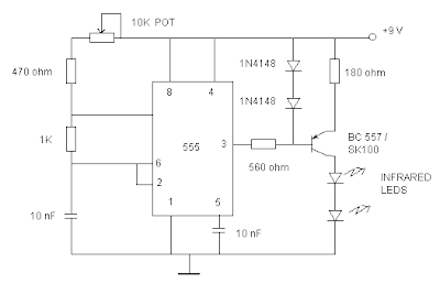
TV Remote Blocker


The 555 IC is wired as an astable multivibrator for a frequency of nearly 38 kHz. This is the frequency at which most of the modern TVs receive the IR beam. The transistor acts as a current source supplying roughly 25mA to the infra red LEDs. To increase the range of the circuit simply decrease the value of the 180 ohm resistor to not less than 100 ohm.
It is required to adjust the 10K potentiometer while pointing the device at your TV to block the IR rays from the remote. This can be done by trial and error until the remote no longer responds.

Remote-operated Master Switch


 Generally, a bedside master switch is used to switch on lamps both indoors and outdoors when there is a threat of intruder. This circuit can be used to activate the master switch from the bed without searching for the switch in darkness. It can be activated by the TV remote handset. The security lamps glow for three minutes and then turn off. The circuit is sensitive and can be activated from a distance of up to 25 meters. 


Apparatus Needed to prepare Remote-operated Master Switch Bridge rectifier
·                     Zener iode
·                     Relay
·                     Transistor /SCR
·                     Resistor and Capacitors
·                     IC CA 3130
·                     3way switch

           IR receiver module TSOP 1738 (IRX1) is used to sense the pulsed 38kHz IR rays from the TV remote handset. The IR receiver module has a PIN photodiode and a preamplifier enclosed in an IR filter epoxy case. Its open-collector output is 5 volts at 5mA current in the standby mode. In the standby mode, no IR rays from the remote handset fall on the IR receiver, so its output pin 3 remains high and LED1 doesn’t glow. Through resistor R2, the base of transistor T1 remains high and it does not conduct. As a result, the voltage at pin 3 of IC CA3130 (IC1) remains low.
         The potential divider comprising resistors R4 and R5 maintains half of 5.1V at pin 2 of IC1. In brief, the voltage at pin 2 of IC1 is higher than at pin 3 and its output remains low. LED2 remains ‘off’ and transistor T2 does not conduct. Relay RL1 remains de-energised and, as a result, security lamps (both indoors and
outdoors) remain switched off.
           When you press any key of the remote TV handset, IR rays fall on the receiver (IRX1) and its output goes low. LED1 flashes in sync with pulsation of the IR rays. At the same time, transistor T1 (BC558) conducts to take pin 3 of IC1 high. IC1 is used as a comparator with timer action.
            When transistor T1 conducts, pin 3 of IC1 gets a higher voltage than pin 2 making the output of IC1 high. Meanwhile, capacitor C4 charges to full voltage and keeps pin 3 high for a few minutes even after T1 is non-conducting. Resistor R3 provides discharge path for capacitor C4, which decides the time period for which the output of comparator IC1 should remain high. The high output of IC1 energises relay RL1 through relay-driver transistor T2. Thus the load, i.e., security lamps, turn on for three to four minutes. LED2 glows to indicate activation of the relay as well as switching ‘on’ of the security lights. Connect a single-pole, single-throw ‘on’/‘off’ switch (MS) to activate the security lamps manually when required.
          Zener diode ZD1 provides 5.1V DC for safe operation of the IR receiver and associated circuit. Power for the circuit is derived from a step-down transformer (X1) and a bridge rectifier comprising diodes D1 through D4. Smoothing capacitor C1 removes ripples, if any, from the power supply. Assemble the circuit on a general purpose PCB and enclose in a suitable cabinet. Drill holes on the front panel for mounting the IR sensor and LEDs. Connect the master switch between the normally-open (N/O) contact and pole of relay RL1 so that the master switch can be used when needed. The relay contacts rating should be more than 4A. Mount the unit near the master switch using minimal wiring

Electronic Candles

          Here is a simple circuit that can produce the effect of candle light in a normal electric bulb. A candle light, as we all know,resembles a randomly flickering light. So, the objective of this project activity is to produce a randomly flickering light effect in an electric bulb.


           To achieve this, the entire circuit can be divided into three parts. The first part comprises IC1 (555), IC2 (74LS164), IC3 (74LS86), IC4 (74LS00) and the associated components. These generate a randomly changing train of pulses. The second part of the circuit consists of SCR1 (C106), an electric bulb connected between anode of SCR1 and mains live wire, and gate trigger circuit components. It is basically half-wave AC power being supplied to the electric bulb. The third part is the power supply circuit to generate regulated 5V DC from 230V AC for random signal generator. It comprises a step down transformer (X1), full-wave rectifier (diodes D3 and D4), filter capacitor (C9), followed by a regulator (IC5). The random signal generator of the circuit is built around an 8-bit serial in/parallel out shift register (IC2). Different outputs of the shift register IC pass through a set of logic gates (N1 through N5) and final output appearing at pin 6 of gate N5 is fed back to the inputs of pins 1 and 2 of IC2. The clock signal appears at pin 8 of IC2, which is clocked by an astable multivibrator configured around timer (IC1). The clock frequency can be set using preset VR1 and VR2. It can be set around 100 Hz to provide better flickering effect in the bulb.
           The random signal triggers the gate of SCR1. The electric bulb gets AC power only for the period for which SCR1 is fired. SCR1 is fired only during the positive half cycles. Conduction of SCR1 depends upon the gate triggering pin 3 of IC2, which is random. Thus, we see a flickering effect in the light output. Assemble the circuit on a general purpose PCB and enclose it in a suitable case. Fix bulb and neon bulb on the front side of the cabinet. Also, connect a power cable for giving AC mains supply to the circuit for operation. The circuit is ready to use. Warning. Since the circuit uses 230V AC, care must be taken to avoid electric shock

fRIENDLY CHARGER FOR MOBILE PHONES

Most mobile chargers do not have current/voltage regulation or short-circuit protection. These chargers provide raw 6-12V DC for charging the battery pack. Most of the mobile phone battery packs have a rating of 3.6V, 650mAh.  For increasing the life of the battery, slow charging at low current is advisable. Six to ten hours of charging at 150-200mA current is a suitable option. This will prevent heating up of the battery and extend its life. 


   The circuit described here provides around 180mA current at 5.6V and protects the mobile phone from unexpected voltage fluctuations that develop on the mains line. So the charger can be left ‘on’ over night to replenish the battery charge. The circuit protects the mobile phone as well as the charger by immediately disconnecting the output when it senses a voltage surge or a short circuit in the battery pack or connector. It can be called a ‘middle man’ between the existing charger and the mobile phone. It has features like voltage and current regulation, over-current protection, and high- and low-voltage cut-off. An added speciality of the circuit is that it incorporates a short delay of ten seconds to switch on when mains resumes following a power failure. This protects the mobile phone from instant voltage spikes.
   The circuit is designed for use in conjunction with a 12V, 500mA adaptor (battery eliminator). Op-amp IC CA3130 is used as a voltage comparator.
It is a BiMOS operational amplifier with MOSFET input and CMOS output. Inbuilt gate-protected p-channel MOSFETs are used in the input to provide very high input impedance. The output voltage can swing to either positive or negative (here, ground) side. The inverting input (pin 2) of IC1 is provided with a variable voltage obtained through the wiper of potmeter VR1. The non-inverting input (pin 3) of IC1 is connected to 12V stabilised DC voltage developed across Zener ZD1. This makes the output of IC1 high.
       After a power resumption, capacitor C1 provides delay of a few seconds to charge to a potential higher than of inverting pin 2 of CA3130, thus the output of IC1 goes high only after the delay. In the case of a heavy power line surge, zener diode ZD1 (12V, 1W) will breakdown and short pin 3 of IC1 to ground and the output of IC1 drops to ground level. The output of IC1 is fed to the base of npn Darlington transistor BD677 (T2) for charging the battery. Transistor T2conducts only when the output of IC1 is high.
During conduction the emitter voltage of T2 is around 10V, which passes  through R6 to restrict the charging current to around 180 mA.Zener diode ZD2 regulates the charging voltage to around 5.6V.
When a short-circuit occurs at the battery terminal, resistor R8 senses the over-current, allowing transistor T1 to conduct and light up LED1. Glowing of LED2 indicates the charging mode, while LED1 indicates short circuit or over-current status. The value of resistor R8 is important to get the desired current level to operate the cut-off. With the given value of R8 (3.3 ohms), it is 350 mA. Charging current can also be changed by increasing or decreasing the value of R7 using the ‘I=V/R’ rule. Construct the circuit on a common PCB and house in a small plastic case.Connect the circuit between the output lines of the charger and the input pins of the mobile phone with correct polarity.

Clap Switch

Here’s a clap switch free from false triggering. To turn on/off any appliance, you just have to clap twice. The circuit changes its output state only when you clap twice within the set time period. Here, you’ve to clap within 3 seconds


Things need to prepare this:
·                     Resistor & capacitor 
·                     IC555
·                     Condenser Microphone
·                     IC4017
·                     LED
·                     Relay....


       The clap sound sensed by condenser microphone is amplified by transistor T1. The amplified signal provides negative pulse to pin 2 of IC1 and IC2, triggering both the ICs. IC1, commonly used as a timer, is wired here as a monostable multi vibrator. Trigging of IC1 causes pin 3 to go high and it remains high for a certain time period depending on the selected values of R7 and C3. This ‘on’ time (T) of IC1 can be calculated using the following relationship:


T=1.1R7.C3 seconds where R7 is in ohms and C3 in micro farads.


           On first clap, output pin 3 of IC1 goes high and remains in this standby position for the preset time. Also, LED1 glows for this period. The output of IC1 provides supply voltage to IC2 at its pins 8 and 4. Now IC2 is ready to receive the triggering signal. Resistor R10 and capacitor C7 connected to pin 4 of IC2 prevent false triggering when IC1 provides the supply voltage to IC2 at first clap. On second clap, a negative pulse triggers  IC2 and its output pin 3 goes high for a time period depending on R9 and C5. This provides a positive pulse at clock pin 14 of decade counter IC 4017 (IC3). Decade counter IC3 is wired here as a bistable. Each pulse applied at clock pin 14 changes the output state at pin 2 (Q1) of IC3 because Q2 is connected to reset pin 15. The high output at pin 2 drives transistor T2 and also energizes relay RL1. LED2 indicates activation of relay RL1 and on/off status of the appliance. A free-wheeling diode (D1) prevents damage of T2 when relay de-energizes. This circuit costs around Rs 80 

Telephone call recorder


Today telephone has become an integral part of our lives. It is the most widely used communication device in the world. Owing to its immense popularity and widespread use, there arises a need for call recording devices, which find application in call centres, stock broking firms, police, offices, homes, etc.


 Here we are describing a call recorder that uses very few componentsBut in order to understand its working, one must first have the basic knowledge of standard telephone wiring and a stereo plug. 
     In India, landline telephones primarily use RJ11 wiring, which has two wires—tip and ring. While tip is the positive wire, ring is the negative one. And together they complete the telephone circuit. In a telephone line, voltage between tip and ring is around 48V DC when handset is on the cradle (idle line). In order to ring the phone for an incoming call, a 20Hz AC current of around 90V is superimposed over the DC voltage already present in
the idle line.  The negative wire from the phoneline goes to IN1,  while the positivewire goes to IN2. Further, thenegative wire from OUT1 and the positive wire from OUT2
are connected to the phone. All the resistors used are 0.25W  carbon film resistors and all the capacitors used are rated for 250V or more.
      The negative terminal of ‘To AUX IN’ is connected to pin 1 of the stereo jack while the positive terminal is connected to pins 2 and 3 of the stereo jack. This stereo jack, in turn, is connected to the AUX IN of any recording device, such as computer, audio cassette player, CD player, DVD player, etc. Here we shall be connecting it to a computer.
    When a call comes in, around 90V AC current at 20Hz is superimposed over the DC voltage already present in the idle line. This current is converted into DC by the diodes and fed to resistor R1, which reduces its magnitude and feeds it to LED1. The current is further reduced in magnitude by the resistor R2 and fed to the right and left channels of the stereo jack, which are connected to the AUX IN port of  a computer.
     Any audio recording software, such as AVS audio recorder, Audacity audio recorder  can be used to record the call. When a call comes in, one needs to launch the audio recording software and start recording. For phone recording, simply connect the stereo jack to the AUX IN port of the PC. Install the audacity audio recorder (different versions are available for free for different operating systems at http://audacity.
sourceforge.net/) on your PC. Run the executable audacity file. In the main window, you will find a drop down box in the top right corner. From this box, select the AUX option. Now you are ready to record any call. As soon as a call comes in, press the record button found in the audacity main window and then pick up the telephone receiver and answer the
call. Press the stop button once the call ends. Now go to the file menu and select the ‘Export as WAV’ option and save the file in a desired location. You may change the value of resistor R2 if you want to change the output volume. you can use a variable resistor in series with R2 to vary the volume of the output. The recorded audio clip can be edited using different options in the audacity software.


      You can assemble the circuit on a general-purpose PCB and enclose it in a small cabinet. Use an RJ11 connector and stereo jack for connecting the telephone set and computer (for call recording). Telephone cords can be used to connect to the phone line and the circuit. Use of a shielded cable is recommended to reduce disturbances in the recording. These can also be reduced by increasing the value of R2 to about 15 kilo-ohms.
EFY note. Audacity recording software is included in this month’s EFY-CD under ‘utilities’ section. 


Water-Level Controller


         In most houses, water is first stored in an underground tank (UGT) and from there it is pumped up to the overhead tank (OHT) located on the roof. People generally switch on the pump when their taps go dry and switch off the pump when the overhead tank starts overflowing. This results in the unnecessary wastage and sometimes non-availability of water in the case of emergency. The simple circuit presented here makes this system automatic, i.e. it switches on the pump when the water level in the overhead tank goes low and switches it off as soon as the water level reaches a pre-determined level. It also
prevents ‘dry run’ of the pump in case the level in the underground tank goes below the suction level. 

                 
           In the figure, the common probes connecting the underground tank and the overhead tank to +9V supply are marked ‘C’. The other probe in underground tank, which is slightly above the ‘dry run’ level, is marked ‘S’. The low-level and high-level probes in the overhead tank are marked ‘L’ and ‘H’, respectively. When there is enough water in the underground tank, probes C and S are connected through water. As a result, transistor T1 gets forward biased and starts conducting. This, in turn, switches transistor T2 on. Initially, when the
overhead tank is empty, transistors T3 and T5 are in cut-off state and hence pnp transistors T4 and T6 get forward biased via resistors R5 and R6, respectively. As all series-connected transistors T2, T4, and T6 are forward biased, they conduct to energise relay RL1 (which is also connected in series with transistors T2, T4, and T6). Thus the supply to the pump motor gets completed via the lower set of relay contacts (assuming that switch S2 is on) and the pump starts filling the overhead tank.
         Once the relay has energised, transistor T6 is bypassed via the upper set of contacts of the relay. As soon as the water level touches probe L in the overhead tank, transistor T5 gets forward biased and starts conducting. This, in turn, reverse biases transistor T6, which then cuts off. But since transistor T6 is bypassed through the relay contacts, the pump continues to run. The level of water continues to rise. 

          When the water level touches probe H, transistor T3 gets forward biased and starts conducting. This causes reverse biasing of transistor T4 and it gets cut off. As a result, the relay de-energises and the pump stops. Transistors T4 and T6 will be turned on again only when the water level drops below the position of L probe. Presets VR1, VR2, and VR3 are to be adjusted in such a way that transistors T1, T3, and T5 are turned on when the water level touches probe pairs C-S, C-H, and C-L, respectively. Resistor R4
ensures that transistor T2 is ‘off’ in the absence of any base voltage. Similarly, resistors R5 and R6 ensure that transistors T4 and T6 are ‘on’ in the absence of any base voltage. Switches S1 and S2 can be used to switch on and switch off, respectively, the pump manually.


You can make and install probes on your own as per the requirement and facilities available. However, we are describing here how the probes were made for this prototype.